Baud Rate Generator (UART)
My previous post was about UART Protocol overview and its working. Today’s post will mainly focus for its internal structure and How one can actual build this protocol using Hardware description language (HDL).
UART consists of 3 modules or in other words parts which all together work for serial data communication in any device.These 3 modules are instantiated in the main module normally termed as Top Module. These modules are:-
- Baud_rate_generator (for synchronization of data transfer)
- UART_transmitter (to transmit the serial data)
- UART_receiver (to receive the serial data)
This post will mainly focus on the 1st module i.e. Baud_Rate_Generator.
Baud Rate:
It is the speed of transferring data from the transmitter to a receiver in the form of bits per second or we can say that number of signal units transferred per second.
The higher a baud rate more data can be transferred in less amount of time.
Baud Rate Generator:-
· Baud rate generator determines transmission speed in asynchronous communication.
It is number of symbols per second transferred.
· Each bit is 1/(baud rate) wide.
· Baud rate = clock frequency/(16*divisor)
Some standard baud rate:
1. 2400
2. 9600 (Mostly used)
3. 19200

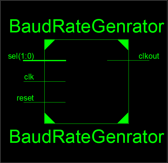
This is designed using Verilog HDL language, as this part is to provide the speed of data transmission it uses a clock(clk) , reset and a multiplexer dor selecting the speed of data transfer. clock out (clkout) is the output signal which is then provided as the input to further modules.
Verilog code :-
module braud_rate_generator(clockout,clk,reset,sel);
input [1:0]sel;
input clk,reset;
output reg clockout=0;
reg[11:0]modulus=12'd0;
reg[11:0]count=0;
always@(sel)
begin
case(sel)
2'b00:modulus=12'd1303;
2'b01:modulus=12'd325;
2'b10:modulus=12'd162;
2'b11:modulus=12'd64;
default:modulus=12'd325;
endcase
end
always@(posedge clk,negedge reset)
begin
if (!reset)
begin
clockout<=0;
end
else if(count==modulus)
begin
count=0;
clockout<=~clockout;
end
else
begin
count=count+1;
clockout<=clockout;
end
end
endmodule

This is the front end design for the module one can test this module by writing the test bench and checking its behavior for different inputs.
Tool used:- Xiline design suite and Isim simulator
Hope you find this post informative . Keep an eye for my next post which will be on Verilog coding and detailed explanation of other modules.
Thanks for reading.